Article
Jun 11, 2026
VLA Arm
Building a Vision-Language-Action Robotic Arm: From a Hierarchical Research Architecture to a Real, Working Pipeline

Why this project exists
Vision-Language-Action (VLA) models — neural networks that take a camera image and a natural-language instruction like "pick the red cube and place it in the bin" and output robot motor commands — have exploded in robotics research over the last two years. Models like RT-2, Octo, OpenVLA, and SmolVLA have shown that a robot can be told what to do in plain English and just... do it.
Almost all of that work happens on $20,000+ research arms with 6-7 degrees of freedom, force-torque sensors, multi-camera rigs, and workstation GPUs. We wanted to know: how much of that is actually reproducible on a $200, 5-servo desktop arm and a Raspberry Pi?
This post walks through the whole project — the original research-grade plan, why we pivoted away from parts of it, the hardware and electrical design, the embedded firmware that turns raw sensors into safety signals, the software bridge into the LeRobot ecosystem, the bugs we hit (including one safety-critical one), and where this goes next.
Part 1 — The Original Vision: A Hierarchical VLA Stack
The project started from a fairly ambitious specification (documented in VLA_Robotic_Arm_Project_Report_FINAL.md): a 4-DOF, 5-servo serial-bus arm built around Feetech STS3215 servos, with:
A Raspberry Pi Camera Module 3 fixed on a rigid overhead post (not arm-mounted — eye-in-hand cameras on low-cost arms tend to destroy their own CSI ribbon cables within a few dozen cycles of joint rotation)
A VL53L5CX 8x8 Time-of-Flight depth array mounted at the wrist, pointed down at the gripper, to get precise grasp-depth (Z) while the overhead camera handled (X, Y)
An ISM330DHCX industrial IMU on the end-effector, sampled at 6.667kHz, used to detect the vibration transient of first contact — a force-torque sensor substitute that costs about $15 instead of $500-2000
An ESP32-WROOM-32 running a 50Hz FreeRTOS control loop on a pinned core (WiFi/BT disabled) for deterministic servo control and hardware-level safety
A Raspberry Pi 5 (8GB) running the full inference stack at ~8Hz: YOLOv8-nano for object detection, a language encoder, SmolVLA-450M + LoRA (with Octo-small as a latency fallback) for skill-conditioned action generation, and an analytical inverse-kinematics safety layer
A hierarchical skill representation — REACH, GRASP, LIFT, PLACE — so the VLA's output is interpretable instead of being a black-box stream of joint deltas, with a target of getting useful behavior from as few as 30 teleoperation demonstrations
The core research bet was: low-DOF arms have no kinematic redundancy (unlike 6-7 DOF research arms), so flat end-to-end VLA models that map pixels straight to joint deltas tend to be unstable. Decomposing the problem into discrete skills, adding a real contact sense that doesn't require a force-torque sensor, and constraining everything with closed-form IK was meant to make a $200 arm behave safely and learn fast.
That document is still the north star for the research framing of the project. But as implementation started, the plan evolved — which is normal, and worth being honest about.
Part 2 — The Pivot: Why We Moved to a Teensy 4.1 + LeRobot Architecture
Two big changes happened between the original spec and what's actually running today:
2.1 ESP32 → Teensy 4.1
The original real-time layer was an ESP32-WROOM-32. During implementation this was replaced with a Teensy 4.1 (600MHz Cortex-M7). The git history tells the story cleanly:
The Teensy 4.1 gives more headroom for the sensor fusion math (ToF frame processing + IMU FIFO draining + contact-oracle RMS, all inside a hard 50Hz loop), has a much simpler native-USB serial story than the ESP32's WiFi-stack-adjacent USB-CDC quirks, and — critically for the safety requirements — runs with no radio at all, eliminating an entire class of scheduling jitter.
2.2 Custom VLA training pipeline → LeRobot + ACT
The original plan specified a from-scratch training pipeline: an HDF5 teleoperation dataset format, a custom skill-segmentation algorithm, and fine-tuning SmolVLA-450M with LoRA on Google Colab.
The current implementation instead builds on LeRobot, Hugging Face's open-source robot-learning framework. Concretely:
The arm is driven through LeRobot's
RoArmM2SFollowerrobot class (a custom addition to LeRobot for the Waveshare RoArm M2-S, a 5x STS3215 arm)Demonstrations are collected with LeRobot's
GamepadTeleopteleoperator and saved as aLeRobotDatasetThe target policy is ACT (Action Chunking Transformer) — the same action-chunking idea referenced in the original spec (predict an 8-step action sequence instead of a single delta), but using LeRobot's well-tested, actively-maintained training and inference code instead of a bespoke pipeline
This is the pragmatic version of the original research bet: keep the parts that matter most for a low-DOF arm — contact sensing without a force-torque sensor, and chunked action prediction — but get there through a maintained framework instead of reinventing dataset formats and training loops. ACT is the centerpiece of the current plan: every other piece of software in this project — the firmware, the sensor bridge, the robot driver, the recording script — exists to feed clean, contact-aware, multi-modal demonstrations into ACT training.
Part 3 — Hardware & Electrical Design
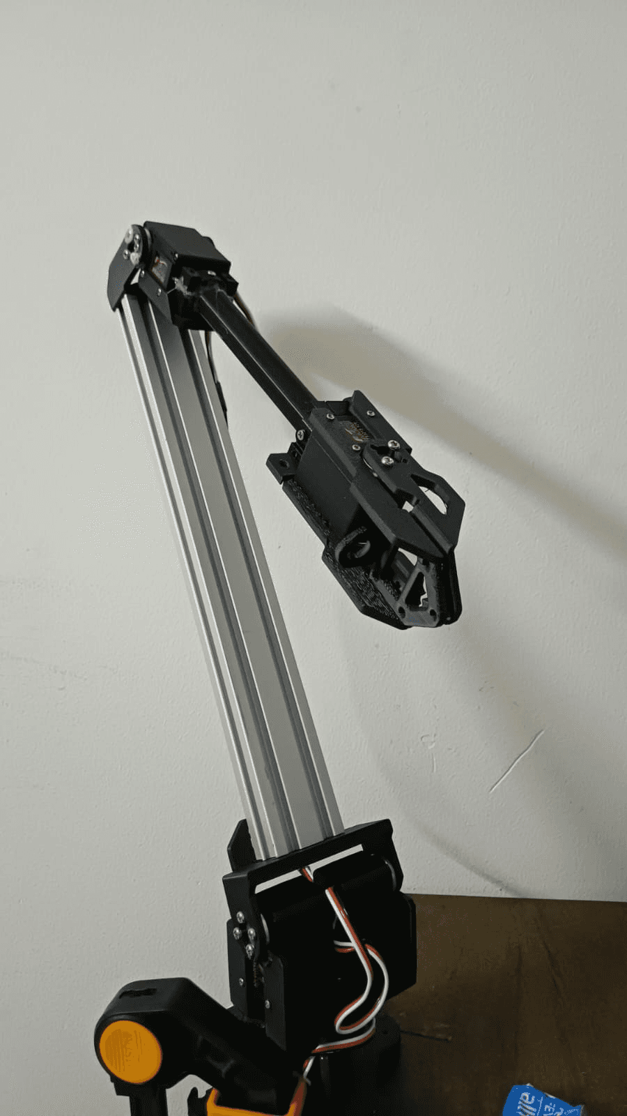
3.1 The arm
A Waveshare RoArm M2-S: five Feetech STS3215 smart serial-bus servos (12V, ~30 kg·cm), driven over a half-duplex UART bus using the SCServo protocol (sync-write for commands, telemetry read-back for position/load/temperature/voltage). Two of the five servos are mechanically coupled to act as a single high-torque shoulder-pitch joint, giving the arm an effective 4-DOF kinematic chain (base yaw, shoulder pitch, elbow/wrist pitch, gripper).
3.2 The sensor co-processor
A Teensy 4.1, wired to:
An ISM330DHCX IMU at I2C address
0x6BA VL53L5CX 8x8 ToF array at I2C address
0x52, with a power-enable line (LPN, pin 2) and an active-low data-ready interrupt (INT, pin 3)Both sensors share the Teensy 4.1's default
Wirebus (SDA=18, SCL=19) — an earlier revision had them on a secondary bus, but they were ported back to the default bus for simplicity (c395502 refactor: port IMU and ToF drivers to Teensy 4.1 default I2C bus)
The Teensy talks to the host (Raspberry Pi 5) over native USB serial at a nominal 115200 baud (the baud rate is actually ignored by Teensy's USB-CDC — it's kept only so the Python pyserial side has a familiar API).
3.3 Power architecture — the one rule that can't be broken
This is the constraint that shows up everywhere in this project's planning docs, and for good reason: servos and compute must never share an unisolated 12V rail.
The five STS3215 servos draw their power from a dedicated 12V rail with its own buck conversion as needed.
The Raspberry Pi 5 and Teensy 4.1 are powered independently — the Teensy specifically runs solely off USB power from the Pi, never from the servo rail.
The reason is simple and unforgiving: servo motors generate large transient current draws and back-EMF spikes when they start, stop, or stall. A shared, unisolated rail means those transients show up as voltage sags and noise on the compute side — at best causing brownout resets on the Teensy mid-control-loop (very bad for a system whose entire job is to catch hard contacts), at worst damaging the Pi. Isolating the rails turns a "the robot randomly reboots when the gripper closes hard" debugging nightmare into a non-issue from day one.
Part 4 — The Firmware: A 50Hz Sensor & Safety Co-Processor
The Teensy 4.1 firmware (firmware/src/sensor_safety/) has one job, done very precisely: read the IMU and ToF sensors, fuse them into a contact estimate, and stream the result to the host at exactly 50Hz — fast enough that a hard contact during teleoperation or autonomous rollout gets caught within tens of milliseconds.
4.1 The control loop
A few details worth calling out:
elapsedMicrosis a Teensy-native microsecond timer — using it for the 50Hz gate (rather thandelay()) means the loop period stays accurate even as the IMU/ToF read calls take variable time.The ToF array updates at only 15Hz (
TOF_UPDATE_HZ), but the loop still runs at 50Hz —tof_check_ready()simply returns the last good frame if a new one isn't available yet, so the packet rate to the host stays constant even though one of the two sensors is slower.The IMU runs much faster than 50Hz and is read via FIFO batch-drain, so no samples are lost between control-loop ticks — important because the contact oracle needs a clean RMS over a window of recent gyro samples, not a single noisy instantaneous reading.
4.2 The contact oracle
The "contact oracle" is the IMU-vibration-based contact detector from the original spec, simplified to its essentials: it keeps a rolling RMS of gyroscope readings over an 8-sample window (~38ms), and:
contact_flagis set when that RMS crossesSAFETY_CONTACT_THRESHOLD(3.5°/s RMS) — this is the "something touched the gripper" signal, useful for skill-segmentation and as an observation featureestop_activeis set at 3x that threshold — a much harder hit, treated as an emergency stop condition
Two thresholds for two different jobs: the soft one is a signal (useful data for the policy and for segmenting demonstrations), the hard one is a safety trip.
4.3 The wire protocol
Every 20ms, the Teensy emits a 168-byte SensorStatus_t packet:
This is a deliberately simple protocol — a fixed-size struct, a magic number for resync after any USB hiccup, and a trivial additive checksum. On the receiving side, the byte stream is scanned for the magic bytes, and if the checksum doesn't match, the parser slides forward 3 bytes and tries again rather than dropping the whole connection. At 50Hz, losing one packet to a checksum mismatch is invisible; losing the whole stream because of one bad byte is not.
Part 5 — Bridging Hardware to Python: SensorMonitor
On the Raspberry Pi 5 side, firmware/tools/sensor_listener.py implements SensorMonitor — a small background thread that:
Opens the Teensy's serial port
Continuously scans for and parses
SensorStatus_tpackets (validating the checksum)Keeps the latest IMU reading and 8x8 ToF frame available via
latest_observation(), thread-safe behind a lockCalls a user-supplied
on_estop()callback the first timeestop_activeis seen — exactly once, via a one-shot latch (_estop_fired)
It also drains the OS serial buffer down to the most recent complete packet on every poll — if the consumer (the LeRobot recording loop) happens to poll slower than 50Hz for a moment, it should always see fresh data rather than a backlog of stale packets.
This module — parse_packet, compute_checksum, normalize_load, and SensorMonitor — is covered by 12 unit tests (firmware/tools/test_sensor_listener.py), including synthetic packet construction, checksum validation, invalid-ToF-zone clamping (the sensor reports 0xFFFF for "no valid target," which gets clamped to a 4.0m max range), and — as covered in the next section — thread-lifecycle edge cases.
Part 6 — The LeRobot Robot Driver: RoArmM2SFollower
LeRobot models every physical robot as a Robot subclass with a connect(), disconnect(), get_observation(), send_action(), and a declared observation_features / action_features schema. The RoArmM2SFollower (in ~/lerobot/src/lerobot/robots/roarm_m2s/) is the class that makes this specific arm speak that language.
For this project, the key addition is wiring the Teensy sensor stream directly into the robot's observation space:
When the sensor co-processor reports a hard contact (estop_active), the robot object itself disconnects — torque is released on the servo bus immediately, without the recording script or any higher-level policy needing to know anything went wrong. Safety lives at the lowest practical layer.
The driver's observation_features extends the base SO-arm feature set with:
Key | Shape | Source |
|---|---|---|
| (8, 8) | VL53L5CX depth grid, in meters |
| (6,) | accel xyz + gyro xyz |
| (5,) | per-servo |
get_observation() merges the Teensy's latest_observation() with the servo bus's own telemetry — each STS3215 reports a Present_Load register where bits 0-9 are magnitude and bit 10 is direction, normalized here via:
So every observation the policy sees during data collection (and later, during ACT inference) includes not just the wrist camera image and joint positions, but the full 8x8 depth field at the gripper, 6-axis inertial data, and per-joint load — the multi-modal contact sensing from the original spec, delivered through LeRobot's standard observation pipeline instead of a bespoke one.
Part 7 — The Data Collection Pipeline
scripts/record_roarm.py is the operator-facing script for collecting demonstrations. It's built entirely on LeRobot primitives — GamepadTeleop, LeRobotDataset.create(), record_loop() — with project-specific scaffolding from scripts/roarm_recording_extras.py:
Two task phrases, 40 episodes each (80 total): "pick the red cube and place it in the bin" and "pick the blue cube and place it in the bin"
Scene rotation: within each 40-episode block, the staging position cycles through four corners (front-left, front-right, back-left, back-right) every 10 episodes, and the operator is prompted to vary lighting/background at the start of each new position block
This is the deliberate-variation discipline that imitation learning lives or dies by: ACT (and any behavior-cloning policy) will happily memorize "the cube is always in the same spot under the same lighting" if you let it. Rotating position and lighting throughout collection forces the policy to actually attend to the visual and depth observations rather than the episode index.
Each episode goes through LeRobot's record_loop(), which the script wires up with teleop_action_processor, robot_action_processor, and robot_observation_processor from make_default_processors() — the standard LeRobot v3 processor pipeline that turns raw teleop/robot I/O into the dataset's feature schema. Gamepad controls map the left stick to shoulder pan/lift, the right stick to elbow flex, and the triggers to gripper open/close; the d-pad saves or discards an episode.
If the Teensy reports an ESTOP mid-episode, the chain of events is: SensorMonitor.on_estop() → follower.disconnect() → the next bus operation inside record_loop() raises DeviceNotConnectedError (a ConnectionError subclass) → the script catches it, reports how many episodes were already saved, and exits cleanly. Re-running the script resumes into the same dataset — a hard contact costs you the current episode, not the whole session.
Part 8 — A Safety Bug Worth Writing About
While reviewing this pipeline (using a two-stage spec-compliance + code-quality review process), we found a real bug in SensorMonitor.stop() — and it's the kind of bug that's invisible in a quick test but would have been a serious problem on hardware.
The original code:
Looks completely reasonable. But trace through what happens on a real ESTOP:
The
SensorMonitorbackground thread detectsestop_activeand callsself.on_estop()on_estopislambda: follower.disconnect()— anddisconnect(), in some code paths, callsself._sensor_monitor.stop()to clean upstop()is now executing on the monitor's own background thread (becauseon_estop()was called from_run(), which isself._thread's target function)self._thread.join(timeout=2.0)is a thread trying to join itself
Python's threading module raises RuntimeError: cannot join current thread in exactly this situation. So the one moment this code is guaranteed to run — a hard contact during recording — would have thrown an unhandled RuntimeError from inside the safety-stop path.
The fix, with a regression test added first (TDD):
The same fix also covers a second latent issue: calling stop() before start() was ever called, which previously raised RuntimeError: cannot join thread before it is started. Both are now exercised by tests, and _stop.set() — the part that actually matters for halting the read loop — always runs regardless of the thread's state.
This is the kind of bug that's easy to write, easy to miss in a quick smoke test (it only triggers on the actual emergency path), and exactly why the e-stop logic gets unit tests and code review before it ever touches hardware.
Part 9 — Where This Goes Next
The roadmap from here is the standard imitation-learning loop, now that the hardware/firmware/data layers are in place:
Hardware bring-up — wire the Teensy 4.1 + IMU + ToF per the pin map above, flash with PlatformIO (
pio run -e teensy41 -t upload), and verify the 50Hz packet stream and checksum on a live serial connection. Confirm the ToF and IMU respond correctly to physical taps and pokes near the gripper.udev rules — give the Teensy and the servo bus stable device names (
/dev/roarm_teensy,/dev/roarm_servo) so the recording script doesn't depend on enumeration order.Gamepad teleop dry run —
python3 scripts/record_roarm.py --repo_id local/roarm_sensor_check --num_episodes 1, confirmingobservation.tof,observation.imu, andobservation.servo_loadactually land in the dataset schema.Full dataset collection — 80 episodes across the two pick-and-place tasks, with position and lighting rotation as designed.
ACT policy training — train an Action Chunking Transformer on the collected dataset via LeRobot's training scripts. ACT's action-chunking (predicting short sequences of future actions rather than single steps) is a natural fit for a low-DOF arm with no kinematic redundancy — it smooths out the kind of single-step prediction noise that would otherwise translate directly into jerky end-effector motion.
Evaluation and iteration — run the trained policy on the real arm, using the Teensy's contact oracle as both a safety net (autonomous ESTOP on unexpected hard contact) and a diagnostic signal (did the policy actually achieve a controlled grasp, or did it just collide?). Use failures to decide whether more data, more variation, or architecture changes are needed — and iterate.
Closing Thoughts
The throughline of this project is a simple idea applied stubbornly: a $200 arm doesn't need $2000 sensors if you're clever about what you actually need to sense. A 6-axis IMU and an 8x8 depth array, fused on a $30 microcontroller into a 50Hz checksummed stream, give a policy contact-awareness that would otherwise require a dedicated force-torque sensor — and they do it through a protocol simple enough to fit in a single struct and a handful of unit tests.
The architecture has changed since the original spec — ESP32 became Teensy 4.1, a bespoke training pipeline became LeRobot + ACT — but the underlying bet hasn't: that careful sensing and careful engineering at the hardware/firmware boundary is what makes imitation learning actually work on affordable hardware, not just in a research paper's appendix.